Section 11.3 FSM in Action
Controlling Traffic Lights and Pedestrian Crossing Signals.
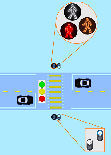
On a small city street, vehicles and pedestrians need to move safely and efficiently (traffic and pedestrian flows are unpredictable). The task lies in coordinating the traffic lights and pedestrian crossing signals.
Safety is top priority, but must not hinder or disrupt the flow of vehicles:
- The traffic light prioritizes vehicle movement when no pedestrians are present (reducing unnecessary stops and congestion). However, when a pedestrian presses the crosswalk button (on either side of the street), the system ensures that vehicles slow down and come to a complete stop, allowing pedestrians to cross safely.
- Small preset delays are introduced to give both drivers and pedestrians enough time to react safely, this will significantly reduce the likelihood of accidents or confusion (ex. The time for yellow light for cars, and the flashing orange light for pedestrians).
- Additionally, the system must ensure that there is no simultaneous conflicting signal, where cars and pedestrians are told to move at the same time, which could lead to dangerous situations.
To tackle these requirements, a state machine-based traffic control system is installed. This system reacts to pedestrian inputs (pressing a crosswalk button) and to an internal automatic timer to regulate traffic flow.
Subsection 11.3.1 Problem Overview (System model and States)
Breaking down a full lifecycle of traffic signaling into distinctive states:
- State \(s_{0}\) : Regular Traffic Flow (Initial state): This is the initial state with normal traffic flow (with green lights for vehicles and red lights for pedestrians): there are no pedestrians, this ensures efficient movement for vehicles.
- State \(s_{1}\) : Pedestrian Request to Cross: When pedestrians are present, and the crosswalk button is pressed (at least once and from either side of the road), the system transitions to this state. The car light stays green for a few seconds to avoid immediately disrupting traffic flow.
- State \(s_{2}\) : Slowing Down Traffic: After waiting for a short interval, the system transitions to State 2, turning the traffic light yellow to signal cars to slow down and prepare to stop. Pedestrians are still waiting (the traffic is about to halt for them).
- State \(s_{3}\) : Stopping Traffic: In this state, the traffic light turns red, bringing vehicles to a stop. However, pedestrians still need to wait for a few more seconds to ensure that all cars have fully halted, and the intersection is safe for crossing. This state is a critical buffer period for added safety.
- State \(s_{4}\) : Pedestrians Cross: Here, the pedestrian signal turns white (steady), allowing pedestrians to cross the road. During this time, traffic is fully stopped, and the intersection is exclusively reserved for pedestrian movement. Pedestrians are given a reasonable amount of time to cross the road.
- State \(s_{5}\) : Warning Pedestrians to Hurry: In this state, the pedestrian signal begins flashing orange, warning pedestrians that the signal is about to turn red, and that they need to hurry and complete their crossing before traffic resumes.
- State \(s_{6}\) : Pedestrians Stop: Now, the pedestrian light is red again, signaling that crossing is no longer allowed. At this point, traffic lights remain red for a brief period to ensure there are no pedestrians left in the intersection.
- State \(s_{7}\) : Traffic Resumes with Holding Time: Finally, the traffic light turns back green again, allowing vehicles to move once more. This is a hold phase to allow traffic to flow before the intersection returns to its initial state and is ready to process pedestrian request to cross (this hold time is essential to avoid traffic congestion).
Subsection 11.3.2 Solution
Example 11.3.2. Blueprints: States, Inputs and Outputs.
Example 11.3.3. State Machine Engine.
Example 11.3.4. Model Definition and Instantiation.
Example 11.3.5. Visualize the Finite State Machine Model.
Example 11.3.6. Running the State Machine (Simulation).
A More Challenging Example.
Similar to the previous use case, except that this time, we have a more complex 4-ways intersection, with dedicated left-turn lanes controlled via left-arrow signal, in addition, we want to allow right-turn-on-red while the left-turn signal is enabled for the other way. Both left and right turn arrows have 3 distinct states that need to be managed and synchronized with the rest of signals, inputs and timers.
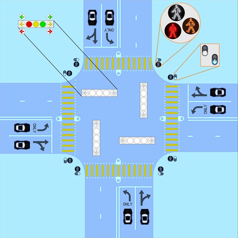
Once again, in the absence of pedestrians, we want to prioritize traffic movement. But also have built-in transition buffer before allowing pedestrian crossing or resuming vehicles traffic.
